

Master three-way ball valve selection for industrial piping systems. This technical guide covers L-Port vs T-Port flow geometries, 2-seat vs 4-seat sealing architectures, seat material temperature thresholds (PTFE/RPTFE/PPL/Metal), and actuator torque calculation formulas with safety factors. Essential reading for pipeline engineers and system designers.
- 1. Introduction: The Engineering Case for Three-Way Ball Valves
- 2. Flow Geometry Deep-Dive: L-Port vs T-Port Configurations
- 3. Seating Architecture: 2-Seat vs 4-Seat Designs & Flow Direction Restrictions
- 4. Seat Material Selection by Temperature & Pressure
- 5. Actuator Sizing & Torque Calculation Methodology
- 6. Installation Best Practices: Water Hammer Prevention & Thermal Relief
- 7. RFQ Engineering Specification Checklist
- 8. References & Industry Standards
1 Introduction: The Engineering Case for Three-Way Ball Valves
In complex industrial piping networks—such as cooling water circuits, chemical distribution loops, thermal oil systems, and water treatment bypass stations—managing flow direction efficiently remains a primary engineering challenge that directly impacts system reliability and operational costs.
Conventional approaches using multiple two-way isolation valves to achieve flow diverting, mixing, or bypassing often result in bulky piping footprints, increased pressure drop points (typically 3-5 additional welded joints per switching function), and complex automation programming with higher failure rates.
A three-way ball valve consolidates flow switching into a single, highly efficient valve body, reducing potential leak paths by up to 60% compared to multi-valve alternatives. However, improper selection of port configurations, seat materials, or flow direction can lead to unwanted cross-contamination, premature seat damage, or catastrophic system-wide water hammer events.
This engineering guide provides pipeline system designers, equipment engineers, and technical project leads with the fundamental principles, selection matrices, and calculation methods required to correctly specify and integrate three-way ball valves into industrial flow control systems.
Secondary keywords: L-port vs T-port ball valve, 2-seat vs 4-seat valve design, actuator torque calculation, valve seat material temperature limits
2 Flow Geometry Deep-Dive: L-Port vs T-Port Configurations
The core functional differentiation in a three-way ball valve lies in the internal drilling pattern of the spherical ball element. Engineers must select between an L-Port (diverting) and a T-Port (mixing/diverting/straight-through) configuration based on the required flow logic and system architecture.
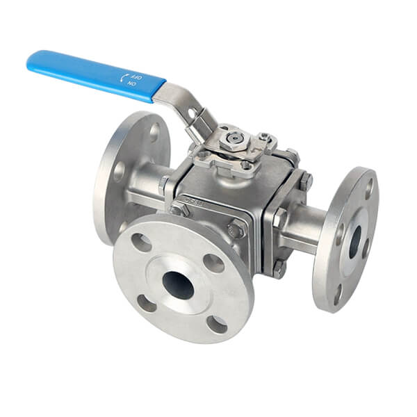
L-Port Ball Geometry (3-Way, 2-Seat or 4-Seat)
An L-Port ball features two flow passages drilled at 90 degrees relative to each other, forming an “L” shape within the spherical body.
| Parameter | Specification |
|---|---|
| Primary Function | Strictly diverting/switching flow from one common inlet to one of two outlets (or reverse) |
| Actuator Rotation | Standard 90° travel |
| Port Connectivity | Cannot connect all three ports simultaneously |
| Typical Applications | Cooling water line switching between primary heat exchanger and standby chiller; dual-filter bypass switching |
Flow Paths:
- Position A: Port 1 → Port 2 (Port 3 closed)
- Position B: Port 1 → Port 3 (Port 2 closed)
- No “all-open” or “all-closed” position available on standard L-Port designs
T-Port Ball Geometry (3-Way, 4-Seat)
A T-Port ball features a straight-through channel intersected by a third perpendicular channel, creating a “T” shaped passage that enables more versatile flow control.
| Parameter | Specification |
|---|---|
| Primary Function | Mixing, diverting, or straight-through flow with bypass capability |
| Actuator Rotation | 90° or 180° travel depending on required position logic |
| Port Connectivity | Can connect all three ports simultaneously (mixing/diverting mode) |
| Typical Applications | Temperature blending stations (hot + cold → mixed outlet); reactor feed switching; multi-source distribution manifolds |
Flow Path Options (with 180° rotation):
1. Mixing mode: Port 2 + Port 3 → Port 1
2. Diverting mode: Port 1 → Port 2 + Port 3
3. Straight-through: Port 2 ↔ Port 3 (Port 1 isolated)
4. Full closure: No flow through any port (available on some 4-seat variants)
Figure 1: L-Port vs T-Port Flow Pattern Comparison
(Image alt text: “L-port ball valve with 90-degree flow passages for diverting applications vs T-port ball valve with intersecting straight-through and perpendicular passages for mixing and bypass applications – NSW VALVE technical diagram”)
- Need to switch a cooling line between primary heat exchanger and standby chiller? → Select L-Port
- Need to mix hot water and cold water to achieve a precise process temperature setpoint? → Select T-Port
- Need both mixing AND diverting in the same application? → Select T-Port with 180° actuator
3 Seating Architecture: 2-Seat vs 4-Seat Designs & Flow Direction Restrictions
A frequently overlooked failure mode in three-way ball valve installations is selecting a 2-seat body design for an application that requires positive isolation from any port—particularly when the system may undergo future modifications or flow reversals.
Critical Seating Distinction
| Feature | 2-Seat Design | 4-Seat Design |
|---|---|---|
| Seal Coverage | Seals only against the two side ports | Encapsulates ball with seals at ALL four quadrants |
| Inlet Restriction | Bottom port MUST be the pressurized entry port | Allows flow entry from ANY port |
| Isolation Capability | Cannot positively isolate the third port when blocked | Provides positive shut-off in ANY position |
| Cost | Lower (fewer sealing components) | Higher (additional pre-loaded seat rings) |
| Torque Requirement | Lower dynamic friction | Higher breakaway torque due to continuous 4-point contact |
Flow Direction Restrictions
2-Seat L-Port Valves:
- Require the common inlet flow to always enter through the bottom port (Port 1)
- Pressure from the bottom port pushes the ball upward against the active seat seal, enhancing sealing
- Critical warning: If pressure is applied from Port 2 or Port 3 when the valve is closed, line pressure will unseat the ball, causing internal bypass and potential cross-contamination
- No bidirectional sealing capability
4-Seat Valves (True Universal Isolation):
- Incorporate pre-loaded seat rings (typically stainless-steel spring-energized PTFE or PPL carriers) at all four sealing quadrants
- Allow full bidirectional pressure sealing regardless of which port acts as the inlet
- Ideal for systems where flow direction may change during normal operation or maintenance bypass scenarios
- Required for safety-critical applications where positive isolation is mandatory
For new projects where future flow reversal is possible, or for critical services where cross-contamination cannot be tolerated, specify a 4-seat design despite the higher initial cost and increased actuator torque requirement.
4 Seat Material Selection by Temperature & Pressure
Three-way ball valves experience significantly higher dynamic friction compared to two-way valves due to continuous surface contact across multiple seat rings. Matching seat materials to media temperatures, pressures, and lubricity characteristics is essential for achieving acceptable service life.
Temperature Thresholds by Seat Material
Figure 2: Operating Temperature Ranges for Common Three-Way Ball Valve Seat Materials
(Image alt text: “Temperature threshold comparison chart for PTFE, RPTFE, PPL, and Stellite metal-seated ball valve trim materials showing maximum continuous operating temperatures from 150°C to 550°C – NSW VALVE engineering reference”)
| Seat Material | Continuous Temp Range | Max Intermittent | Pressure Rating | Key Application Characteristics |
|---|---|---|---|---|
| Virgin PTFE | -20°C to 150°C | 160°C | Class 150 / PN16 | Lowest friction coefficient (0.04-0.08); ideal for pure water, instrument air, and general HVAC loops; limited creep resistance |
| RPTFE (15% Glass-Filled) | -20°C to 180°C | 200°C | Class 150–300 | Enhanced creep resistance (30% improvement over virgin PTFE); standard for medium-pressure steam tracing, hot water, and mild chemical services |
| PPL (Polyphenylene Sulfide-based) | -20°C to 230°C | 250°C | Class 150–600 | High thermal stability with lower cost than metal seats; excellent for district heating, saturated steam, and thermal oil below 230°C |
| Stellite®/Tungsten Carbide Metal | -20°C to 450°C | 550°C | Class 150–1500 | Hardened surface cladding (HRC 38-45); designed for thermal oil above 250°C, abrasive slurries, and high-frequency severe thermal cycling applications |
Seat Material Selection Flowchart
Is media temperature > 230°C?
├─ YES → Select Metal-Seated (Stellite/Tungsten Carbide)
└─ NO → Is media temperature > 180°C?
   ├─ YES → Select PPL (up to 230°C continuous)
   └─ NO → Is media lubricating (water/oil) or non-lubricating (gas)?
      ├─ Lubricating → PTFE (cost-optimized, <150°C)
      └─ Non-lubricating → RPTFE (improved wear resistance, <180°C)
Friction Coefficient & Torque Impact
| Seat Material | Static Friction (μ) | Relative Torque Impact |
|---|---|---|
| PTFE | 0.05–0.08 | Baseline (1.0×) |
| RPTFE | 0.10–0.15 | 1.3–1.5× |
| PPL | 0.20–0.30 | 1.8–2.2× |
| Metal-Seated | 0.35–0.50 | 2.5–3.5× |
Important: The higher friction coefficients of PPL and metal-seated materials must be factored into actuator sizing calculations (see Section 5 below).
5 Actuator Sizing & Torque Calculation Methodology
Automating a three-way ball valve requires careful torque calculation to prevent actuator stalling, stem shear, or inadequate sealing under worst-case operating conditions. Because a 4-seat three-way valve maintains continuous contact across four pre-loaded seat seals, its breakaway torque (Tb) is significantly higher than a standard 2-seat floating ball valve of the same nominal size—typically 40-60% higher.
Torque Sizing Formula
To determine the minimum required actuator torque (Ta) under maximum differential pressure (ΔP) conditions:
Where:
- Tb = Base breakaway torque provided by the valve manufacturer (measured at maximum differential pressure and maximum temperature)
- SF = Application Safety Factor (see table below)
Recommended Safety Factors by Service Condition
| Service Condition | Safety Factor (SF) | Engineering Justification |
|---|---|---|
| Clean lubricating liquids (clean water, hydraulic oil, light hydrocarbons) | 1.25 | 25% margin accounts for minor seat wear and viscosity variations |
| Non-lubricating media (air, dry gas, demineralized water, refrigerants) | 1.35–1.50 | Higher coefficient of friction; 35-50% margin recommended |
| Viscous, slurry, or high-temperature media (>180°C) | 1.50–1.60 | Accounts for increased friction at elevated temperatures and potential particulate intrusion into seat contact zone |
| Severe service (abrasive slurries, coking services, high-frequency cycling) | 1.60–1.80 | Consult factory for application-specific torque data |
Sample Torque Calculation
Given:
- 4″ Class 300 three-way ball valve, 4-seat PTFE design
- Manufacturer base breakaway torque (Tb) at 600 psi ΔP: 450 N·m
- Service: Demineralized water at 120°C (non-lubricating)
- Recommended SF: 1.40
Ta = 450 × 1.40 = 630 N·m minimum actuator torque
Select actuator: 630 N·m × 1.05 (actuator-to-valve interface efficiency factor) = 662 N·m → Select next standard actuator size: 700 N·m or 800 N·m model
Pneumatic Actuator Travel Selection
| Actuator Type | Travel Angle | Application |
|---|---|---|
| 90° Double-Acting (Rack & Pinion) | 90° | Standard L-port switching; basic 2-position T-port (mixing OR diverting) |
| 90° Spring-Return (Fail-Safe) | 90° | L-port applications requiring fail-safe positioning (spring-to-close or spring-to-open) |
| 180° Double-Acting (Scotch Yoke) | 180° | T-port valves utilizing all three operating positions (Center-Off / Left-Divert / Right-Divert) |
| 3-Position Actuator with Center-Off | 90° + 90° | Specialized mixing applications requiring an intermediate “all-closed” position |
Referenced Standard: All actuator mounting interfaces should conform to ISO 5211 (direct mounting pad dimensions and stem square sizes). This ensures interchangeability between actuator manufacturers and simplifies future maintenance replacements.
6 Installation Best Practices: Water Hammer Prevention & Thermal Relief
Water Hammer Prevention During High-Speed Actuation
Fast pneumatic switching (stroke times under 0.5 seconds) in large-diameter three-way valves can generate severe hydraulic shock loads due to instantaneous flow deceleration. Water hammer pressures in worst-case scenarios can reach 5-10× normal operating pressure, potentially causing:
- Pipe support displacement
- Flange gasket extrusion
- Valve stem or seat damage
- Downstream instrument failure
Engineering Solution:
- Install pneumatic speed controls (needle valve throttles) on actuator pilot lines
- Adjust stroke time to 2–5 seconds depending on line size and flow velocity
- For line sizes ≥ 6″ or velocities ≥ 3 m/s, consult valve manufacturer for stroke time recommendations
Thermal Expansion Relief in High-Temperature Systems
In high-temperature thermal fluid loops (above 200°C), fluid trapped inside the dead cavity of an isolated ball port can expand rapidly. The volumetric expansion coefficient of most hydrocarbons at 200°C can cause trapped fluid pressure to exceed 10,000 psi—potentially rupturing the ball or distorting the valve body.
Design Requirements:
- Specify valves with cavity relief seats (self-relieving seat grooves)
- Ensure seat design allows trapped fluid to vent to the downstream (lower pressure) side when pressure exceeds seat preload
- For critical applications, specify stem anti-blowout design per ASME B16.34
Mounting Orientation Guidelines
| Mounting Orientation | Impact on Stem Packing | Recommendation |
|---|---|---|
| Stem upright (vertical) | Optimal—prevents particulate accumulation around packing | Preferred orientation for all services |
| Horizontal (stem horizontal) | Acceptable—but potential for accelerated packing wear in abrasive services | Use only when vertical mounting is physically constrained |
| Stem inverted (vertical, stem down) | Particulates settle into packing area, causing rapid leakage and stem binding | Not recommended for any media containing suspended solids |
Standard Valve End Connections
| End Type | Standard | Typical Applications |
|---|---|---|
| Flanged (RF) | ASME B16.5 Class 150/300/600 | General industrial, chemical, oil & gas |
| Flanged (RTJ) | ASME B16.5 Class 600+ | High-pressure gas, hydrogen service |
| Threaded (NPT) | ASME B1.20.1 | Small bore (≤ 2″), instrument tubing |
| Socket Weld (SW) | ASME B16.11 | High-pressure small bore, toxic service |
| Buttweld (BW) | ASME B16.25 | Large diameter, high-integrity piping systems |
7 RFQ Engineering Specification Checklist
When issuing a Request for Quotation (RFQ) or specifying a three-way ball valve for your piping system, confirm the following 8 core parameters:
| # | Parameter | Specification Options | Your Selection |
|---|---|---|---|
| 1 | Flow Geometry | ☐ L-Port (diverting only) / ☐ T-Port (mixing & diverting) | |
| 2 | Rotation Angle | ☐ 90° travel / ☐ 180° travel | |
| 3 | Seat Structure | ☐ 2-Seat (bottom inlet required) / ☐ 4-Seat (universal flow) | |
| 4 | Seat Material | ☐ PTFE (<150°C) / ☐ RPTFE (<180°C) / ☐ PPL (<230°C) / ☐ Metal-Seated (>250°C) | |
| 5 | Pressure Class | ☐ Class 150 / ☐ Class 300 / ☐ Class 600 / ☐ Class 1500 | |
| 6 | End Connections | ☐ Flanged RF / ☐ Flanged RTJ / ☐ Threaded NPT / ☐ Socket Weld / ☐ Buttweld | |
| 7 | Actuation Interface | ☐ Manual Lever / ☐ Pneumatic (DA/ SR) / ☐ Electric / ☐ ISO 5211 mounting pad | |
| 8 | Special Requirements | ☐ Cavity relief seats / ☐ Stem anti-blowout / ☐ NACE MR0175 / ☐ Low-emission packing |
8 References & Industry Standards
| Standard | Title | Relevance |
|---|---|---|
| ASME B16.34 | Valves—Flanged, Threaded, and Welding End | Pressure-temperature ratings, wall thickness, stem design |
| ASME B16.5 | Pipe Flanges and Flanged Fittings | Flange dimensions, facing types (RF/RTJ) |
| ISO 5211 | Industrial Valves—Actuator Mounting | Interface dimensions for direct actuator mounting |
| API 607 / ISO 10497 | Fire Testing of Valves | Fire-safe seat design requirements |
| NACE MR0175 / ISO 15156 | Sulfide Stress Cracking | Materials for sour service (H₂S environments) |
| FCI 70-2 / ANSI/ISA-75.01.01 | Control Valve Seat Leakage Classification | Seat leakage rates for various seat designs |
*Need custom torque charts for specific pressure classes, CAD 3D models in STEP/IGES format, or high-temperature PPL/metal seat datasheets for your piping project?*
Post time: Jul-22-2026